5.1. Analogue multiplier simulation
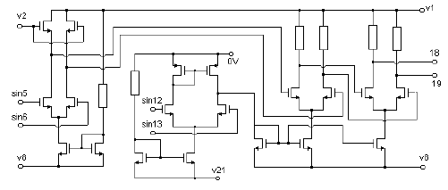
The common way of analog systems modeling is structural description that stands for coupling of components with links and definition of components' parameters. As an example of pure structural description, the analog multiplier shown in Fig. 5.1 will be considered. It consists of 19 MOS transistors, and has the following functional blocks: pre-distortion circuit, voltage controlled current source, and two differential stages. Multiplier output is between nodes 18 and 19. Multiplier is described structurally in a way that circuit elements are first declared:
resistor r1,r2;
meaning that components r1 and r2 are resistors. It is also possible to use implicit declaration:
implicit { resistor r; capacitor c; }

Fig. 5.1: Analog multiplier with MOS transistors
which means that all elements beginning with r are resistors, and all ones beginning with c are capacitors.
After declaring the components to be used, structural description of the multiplier is similar to SPICE circuit description. Nodes where the component is plugged are given in parenthesis, and parameters (including the name of the model card) are given afterwards. A part of the code describing the multiplier is given that shows the instantiation of an MOS transistor.
mp2 (11,10,0,0) { model=PC_PM1; w=1.7u; l=1.2u; ad=150p; as=100p; pd=10p; ps=10p; }
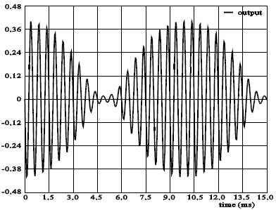
Of course, the model card PC_PM1 must be defined earlier in the simulation library. It has the same syntax as SPICE MOS model, so it will not be described in details here. To demonstrate the simulation of the multiplier depicted in Fig. 5.1, two sine wave signals with different frequencies are brought to its inputs. Multiplier output is an amplitude-modulated signal. The simulation results are given in Fig. 5.2.

Fig. 5.2: Results of analog multiplier simulation